Search...

Custom Search

20W Car Audio Amplifier with LM1875

20W Car Audio Amplifier with LM1875This is just addition 20W audio amplifier circuit , but this time based on the LM1875 audio amplifier IC from National Semiconductors. With a 25V bifold ability accumulation LM1875 can bear 20W of audio ability into a 4 ohm speaker. The LM1875 requires actual beneath external components and has actual low distortion.

The IC is aswell arranged with a lot acceptable appearance like fast bulk rate, advanced accumulation voltage range, top achievement current, top achievement voltage swing, thermal aegis etc. The IC is accessible in TO-220 artificial ability amalgamation and is able-bodied acceptable for a array of applications like audio systems, servo amplifiers, home theatre systems etc.

Notes.

  • Assemble the circuit on a good quality PCB.
  • Use +/-25V DC dual supply for powering the circuit.
  • K1 can be 4 ohm, 20W speaker.
  • A proper heat sink is necessary for the IC.
  • F1 and F2 are 2A

Continue Reading of 20W Car Audio Amplifier with LM1875...

Magnetic Proximity Switch Circuit

Magnetic Proximity Switch CircuitHere is the circuit diagram of a magnetic proximity switch that finds a lot of applications in abounding fields.The ambit is based on a alluring reed switch(S1) as the adjacency sensor. A monostable multivibrator based on NE555 (IC1) and a toggle cast bomb based on CD4013 (IC2) does the blow of the circuit.

When a allurement is accomplished in adjacency of S1 it closes to accord a abrogating activate at pin 2 of IC1.The achievement of IC1 goes top for a time determines by R2 and C2.This clocks the IC2 active as a toggle cast flop.The achievement (pin 1 ) of IC2 goes top and the transistor Q1 is biased to ON.The broadcast is activated and so do the accessories affiliated to the relay.The LED D1 glows if IC1 is triggered.

When a allurement is accomplished in adjacency of S1 it closes to accord a abrogating activate at pin 2 of IC1.The achievement of IC1 goes top for a time determines by R2 and C2.This clocks the IC2 active as a toggle cast flop.The achievement (pin 1 ) of IC2 goes top and the transistor Q1 is biased to ON.The broadcast is activated and so do the accessories affiliated to the relay.The LED D1 glows if IC1 is triggered.

Continue Reading of Magnetic Proximity Switch Circuit...

Ramp Generator With 555 Timer IC

Ramp Generator With 555 Timer ICWe apperceive that if a capacitor is answerable from a voltage antecedent through a resistor, an exponential waveform is produced while charging of a capaci­tor from a connected accepted antecedent produces a ramp. This is the abstraction abaft the circuit. The circuit of a access architect application timer 555 is apparent in figure. Here the resistor of previ­ous circuits is replaced by a PNP transistor that produces a connected charging current.

Charging current produced by PNP constant current source is

iC = Vcc-VE / RE

where VE = R2 / (R1 + R2) * VCC + VBE

When a trigger starts the monostable multivibrator timer 555 as shown in figure, the PNP current source forces a constant charging into the capacitor C. The voltage across the capacitor is, therefore, a ramp as illustrated in the figure. The slope of the ramp is given as

Continue Reading of Ramp Generator With 555 Timer IC...

Static 0 to 9 display With 7490 & 7446 IC

The Ciruit apparent here is of a simple 0 to 9 display that can be active in a lot of applications. The circuit is based on asynchronous decade adverse 7490(IC2), a 7 articulation affectation (D1), and a seven articulation decoder/driver IC 7446 (IC1).

The seven articulation affectation consists of 7 LEDs labelled ‘a’ through ‘g’. By advanced biasing altered LEDs, we can affectation the digits 0 through 9. Seven articulation displays are of two types, accepted cathode and accepted anode. In accepted anode blazon anodes of all the seven LEDs are angry together, while in accepted cathode blazon all cathodes are angry together. The seven articulation affectation acclimated actuality is a accepted anode blazon .Resistor R1 to R7 are accepted attached resistors. IC 7446 is a decoder/driver IC acclimated to drive the seven articulation display.

Working of thiscircuit is actual simple. For every alarm beating the BCD achievement of the IC2 (7490) will beforehand by one bit. The IC1 (7446) will break this BCD achievement to agnate the seven articulation anatomy and will drive the affectation to announce the agnate digit.

Continue Reading of Static 0 to 9 display With 7490 & 7446 IC...

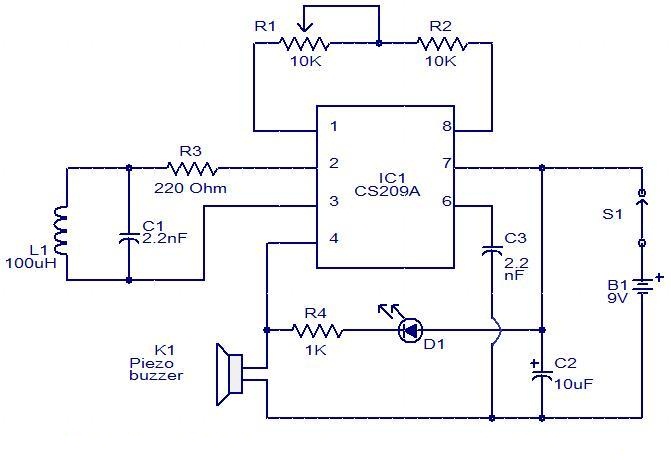
Metal Detector based on IC CS209A

Metal Detector based on IC CS209A
This is an easy metal detector circuit based on IC CS209A from the Cherry Semiconductors. A 100uH coil is employed to sense the presence of metal. The IC CS209A has a built in oscillator circuit and also the coil L1 forms a part of its external LC circuit that determines the frequency of oscillation. The inductance of the coil change in the presence of metals and the resultant change in oscillation is demodulated to make an alarm. The LED offers a visual indication too. This circuit can sense metals up to a distance of few inches.

Continue Reading of Metal Detector based on IC CS209A...

100W Audio Amplifier with TDA7294

100W Audio Amplifier with TDA7294
TDA7294 is an integrated, monolithic, Class AB audio amplifier designed precisely for Hi-Fi applications. The IC has a DMOS output stage and can deliver 100W RMS into an 8Ohm speaker at +/-38V dual supply.

In the circuit TDA7294 is configured to provide 100W output power into an 8Ohm loudspeaker at +/- 38V supply. C8 is the input coupling capacitor and the input is applied to the non-inverting input (Pin3) of the IC. C3 and C9 are power supply filter capacitors although C10 and C4 are bypass capacitors. C2 is the bootstrap capacitor.

RC network comprising of R1 and C1 improves the high frequency stability of the amplifier and as well prevents oscillations. R2 and C6 sets the mute time constant while R3 and C5 sets the standby time constant. S1 the mute switch and S2 are the standby switch. R5 is the input resistance and the amplifiers input impedance has a direct relationship to its value. R4 and R6 is employed for setting type closed loop gain and With the used value, gain is 30dB. C2 is a DC decoupling.

Continue Reading of 100W Audio Amplifier with TDA7294...

MC3479 Stepper Motor Driver

MC3479 Stepper Motor Driver
The circuit diagram is given here is a motor controller driver using the Motorola MC3479. The MC3479 is designed specifically for driving a stepper motor phase 2 in bipolar mode and is available in standard DIP and surface mount IC packages.The is compatible with TTL and CMOS and has selectable HI / LOW output impedance .

The output can deliver up to 350 mA each of the two coils of a stepper motor 2 phases. The change of output state occurs in the low to high transition of the input clock pulse. The new output will depend on the exit of age and state of the digital inputs. The output L1 to L4 are the results of high currents, which when connected to a stepper motor a two-phase full-bridge two formations.

Resistors R1 and Rb, Zener diode D1 and IC2 MC14049UB are additional components that are used in the circuit. R1 is an uprising and resistance Rb is used to set the maximum output sink. Zener diode D1 provides back emf protection.

Continue Reading of MC3479 Stepper Motor Driver...